This week I experimented with using an augmented reality app at a public meeting to display this simple visualization of one of our projects.
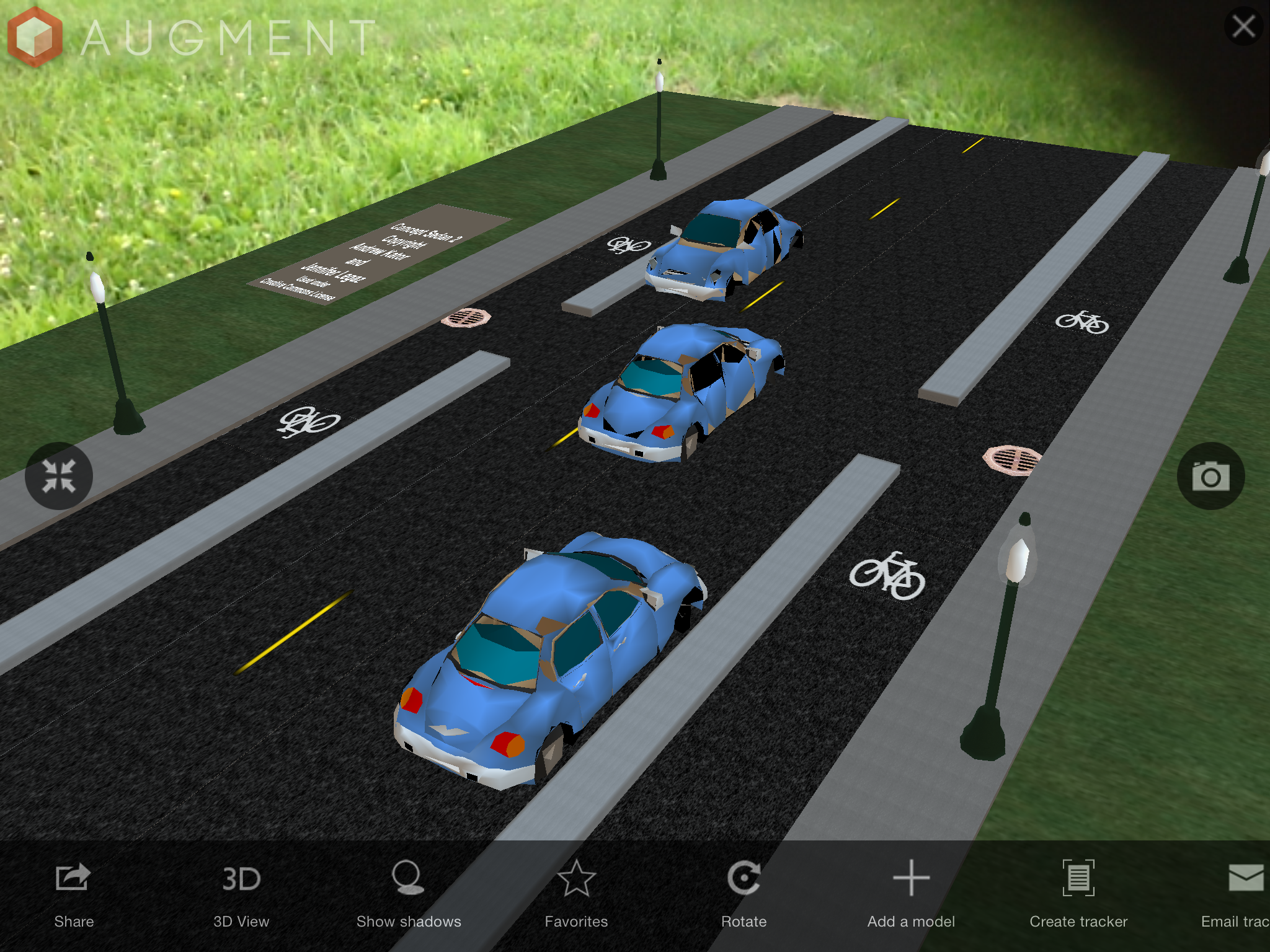
My experience was that it did seem to help with explaining or showing people not only an overall snapshot of how the roadway will look when finished, but it also helped show specific design and operational details that were difficult to describe. So I figured I'd post a quick explanation of the software I used to create the model and which app I used to host and display the visualization in case anyone else is interested in trying something similar out at their own meetings.
To begin, I would have liked to just export the project directly out of CAD and into the program where I assembled the 3D model because this allows for a more accurate representation and saves some steps. I've done this before using AutoCAD, and it was very straight forward and easy. Unfortunately we use Microstation at work instead of AutoCAD and so far I have been unable to find a way to get this to work with that software. The main problem seems to be that although it has 3D export capability, the program will not allow me to export something with a thickness so everything ends up flat. And it won't let me expand my export in the "Z" direction even if I import it into other 3D programs. I've spoken with a representative of the company, and as I've indicated in previous posts, he said Microstation is not interested in supporting this because they don't see a need for engineers to use this type of feature – as he put it "we're engineers, not gamers." So because of this, I had to create the 3D objects in other programs and use a PDF of the plan view as a guide in placing the objects. Also because of this and my time constraints I only modeled a portion of the project where there were no complex shapes.
So the program I used to create and assemble the 3D objects is Opensimulator. It's a free, open source program that runs as a web service and allows you to create and texture 3D objects then export them as models. You can set up Opensimulator on your own desktop by using something like SimonaStick or you can run it by installing it on your computer and connecting it to a service that allows you to access the interface with the use of a viewer. I used the second option and connected it to a service called OSGrid then used the Singularity viewer to log in and build. The main difference between building with this method and one that would use a more traditional 3D program like Blender is that building in Opensimulator is much more intuitive because you create using an avatar or 3D representation of yourself. Opensimulator has also greatly simplified the creation and texturing of objects.
Here is an "aerial view" of what my "build" looked like inside OSGrid right before I exported it as a 3D model.
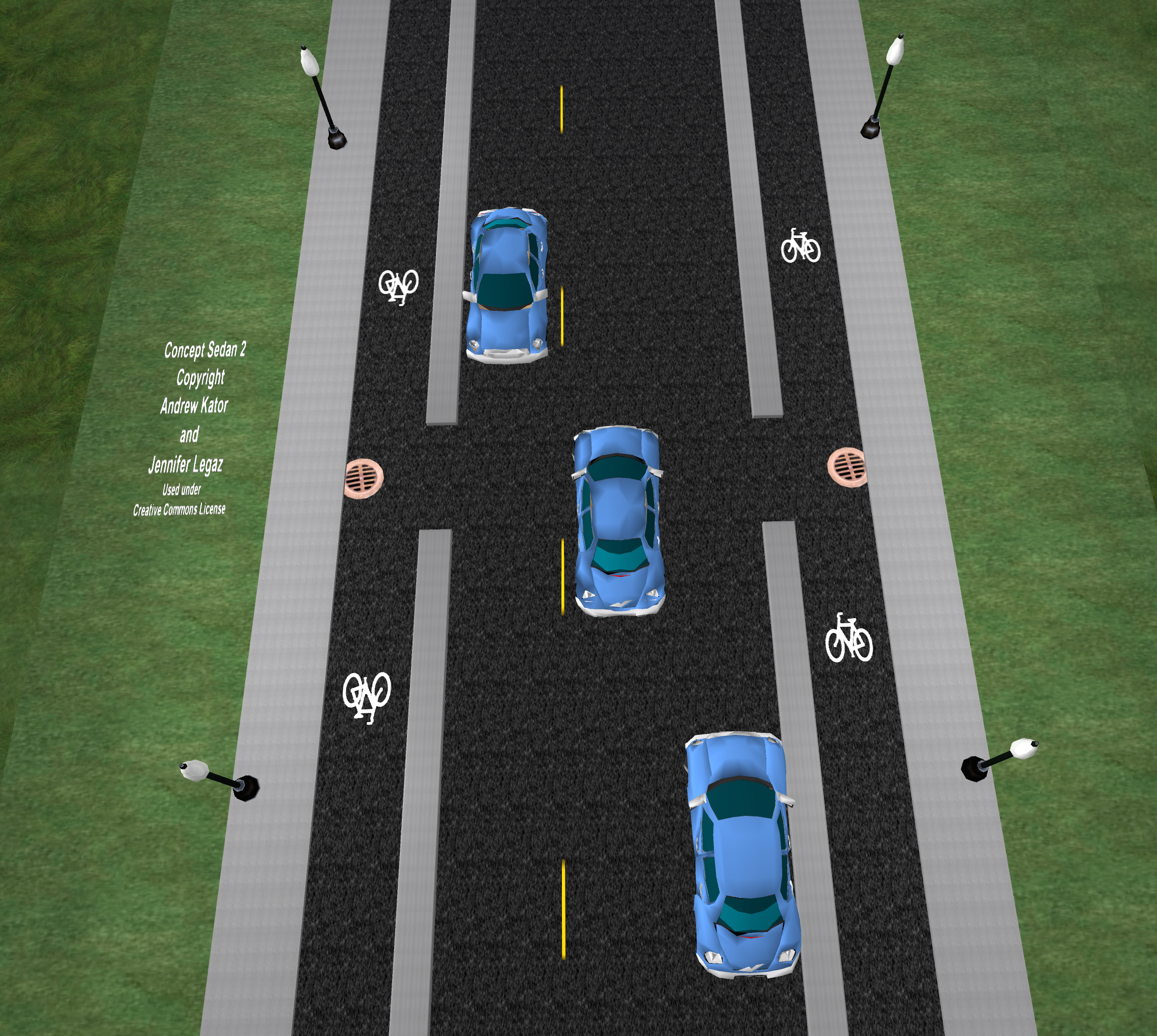
As a side note, what is nice about building in Opensimulator is that you can use your avatar to walk through the project and get a feel for how it will function. If we were also building a streetscape, the use of an avatar helps assist in placement of elements. And from what I understand, if I had an Oculus Rift device, I could have put it on and immersed myself in the design as if I was actually there. This is something I hope to also eventually try as a design tool once I get a chance to buy one of those devices.
The only elements in the photo above that I could not create in Opensimulator were the cars and curbed medians. As you can see from the attribution note in the photo, the cars were 3D models I downloaded from the Kator Legaz website then uploaded into Opensimulator using Singularity. And I also uploaded a median that I created in Blender because I wanted the top to be curved like a regular curb is – Opensimulator does not allow for the creation of something like this so I had to use Blender then import the 3D model into Opensimulator. For all the graphics or textures applied to the models, I created them using a graphic software package then uploaded them into Opensimulator. There are many graphics programs that I use, but if you are looking for a good, free program, you can always use Gimp.
Once everything was assembled, I used the export 3D model feature in Singularity to create a Collada file of my build. Then I used my account on Augment to upload the model so I could access it and view it using the Augment app on my iPhone and iPad. Having the model available at the meeting made it convenient to show people what it will look like when built. For example, when I was having trouble explaining how the inlets impact the bike lane, I was able to just use this model to show someone how the inlets effectively reduce the bike lane from 7.5 feet in width to 5 feet if people do not want to ride over the inlet. Overall I would say having the model did enhance the ability to share our project with the community, and I hope to be able to build upon this experience to create more complex and detailed models in the future. If you want to check out the model yourself, you can access it here:
3D Model of Protected Bike Lane